Introduction to Software Quality
Why Software Quality matters
Let's have a look at one of the most famous bugs of the whole Software History, the bug that AT&T suffered in 1990.
An example of the sequences of Poor Quality Software
What happened?
At 2:25 PM on Monday, January 15th, network managers at AT&T's Network Operations Centre began noticing an alarming number of red warning signals coming from various parts of their network. Within seconds, the network warnings were rapidly spreading from one computer-operated switching Centre to another. The managers tried to bring the network back up to speed for nine hours, while engineers raced to stabilize the network, almost 50% of the calls placed through AT&T failed to go through until at 11:30 PM, when network loads were low enough to allow the system to stabilize.
AT&T alone lost more than $60 million in unconnected calls. Of course, there were many additional consequences difficult to be measured such as business that could be done because relied on network connectivity.
The system was failure tolerant, wasn't it?
AT&T's long-distance network was a model of reliability and strength. On any given day, AT&T's long-distance service, which at 1990 carried over 70% of the US long-distance traffic.
The backbone of this massive network was a system of 114 computer-operated electronic switches (4ESS) distributed across the United States. These switches, each capable of handling up to 700,000 calls an hour, were linked via a cascading network known as Common Channel Signalling System No. 7 (SS7). When a telephone call was received by the network from a local exchange, the switch would asses 14 different possible routes to complete the call. At the same time, it passed the telephone number to a parallel signalling network that checked the alternate routes to determine if the switch at the other end could deliver the call to it's local company. If the destination switch was busy, the original switch sent the caller a busy signal and released the line. If the switch was available, a signal-network computer made a reservation at the destination switch and ordered the destination switch to pass the call, after the switches checked to see if the connection was good. The entire process took only four to six seconds.
What went wrong?
The day the bug popped-up, a team of 100 frantically searching telephone technicians identified the problem, which began in New York City. The New York switch had performed a routine self-test that indicated it was nearing its load limits. As standard procedure, the switch performed a four-second maintenance reset and sent a message over the signalling network that it would take no more calls until further notice. After reset, the New York switch began to distribute the signals that had backed up during the time it was off-line. Across the country, another switch received a message that a call from New York was on it's way, and began to update its records to show the New York switch back online. A second message from the New York switch then arrived, less than ten milliseconds after the first. Because the first message had not yet been handled, the second message should have been saved until later. A software defect then caused the second message to be written over crucial communications information. Software in the receiving switch detected the overwrite and immediately activated a backup link while it reset itself, but another pair of closely timed messages triggered the same response in the backup processor, causing it to shut down also. When the second switch recovered, it began to route it's backlogged calls, and propagated the cycle of close-timed messages and shut-downs throughout the network. The problem repeated iteratively throughout the 114 switches in the network, blocking over 50 million calls in the nine hours it took to stabilize the system.
The roots of the issue
The cause of the problem had come months before. Early December, technicians had upgraded the software to speed processing of certain types of messages. Although the upgraded code had been rigorously tested, a one-line bug was inadvertently added to the recovery software of each of the 114 switches in the network. The defect was a C program that featured a break statement located within an if clause, that was nested within a switch clause. In pseudo-code, the program read as follows:
                1  while (ring receive buffer not empty and side buffer not empty) DO
                2    Initialize pointer to first message in side buffer or ring receive buffer

                3    get copy of buffer

                4    switch (message) {
                5       case (incoming_message):
                6             if (sending switch is out of service) DO {
                7                 if (ring write buffer is empty) DO
                8                     send "in service" to status map
                9                 else
                10                    break
                              } // END IF
                11            process incoming message, set up pointers to optional parameters
                12            break
                     } // END SWITCH
                13   do optional parameter work
When the destination switch received the second of the two closely timed messages while it was still busy with the first (buffer not empty, line 7), the program should have dropped out of the if clause (line 7), processed the incoming message, and set up the pointers to the database (line 11). Instead, because of the break statement in the else clause (line 10), the program dropped out of the case statement entirely and began doing optional parameter work which overwrote the data (line 13). Error correction software detected the overwrite and shut the switch down while it could reset. Because every switch contained the same software, the resets cascaded down the network, incapacitating the system.
Lessons Learned
Unfortunately, it is not difficult for a simple software error to remain undetected, to later bring down even the most reliable systems. The software update loaded in the 4ESSs had already passed through layers of testing and had remained unnoticed through the busy Christmas season. AT&T was fanatical about its reliability. The entire network was designed such that no single switch could bring down the system. The software contained self-healing features that isolated defective switches. The network used a system of "paranoid democracy," where switches and other modules constantly monitored each other to determine if they were "sane" or "crazy." Sadly, the Jan. 1990 incident showed the possibility for all of the modules to go "crazy" at once, how bugs in self-healing software can bring down healthy systems, and the difficulty of detecting obscure load- and time-dependent defects in software.
Software Crisis
But we could think that this bug occurred a while ago and that nowadays we have more advanced technologies, methodologies, training systems and developers.
Is this really true? Just partially, it's true Software Development has evolved a lot, but the type of problems that are solved via Software has also evolved, every day with try to solve more problems and more complex via software.
The Software Crisis term was coined by USA Department of Defence years ago in order to describe that the complexity of the problems addressed of software has outpaced the improvements in the software creation process as shown graphically in .
"Few fields have so large a gap between best current practice and average current practice."
Department of Defence
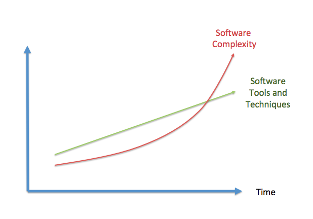
In other words, the software creation process has evolved very little while the problems software is solving are way too much complex
"We have repeatedly reported on cost rising by millions of dollars, schedule delays, of not months but years, and multi-billion-dollar systems that don't perform as envisioned. The understanding of software as a product and of software development as a process is not keeping pace with the growing complexity and software dependence of existing and emerging mission-critical systems."
Government Accounting Office
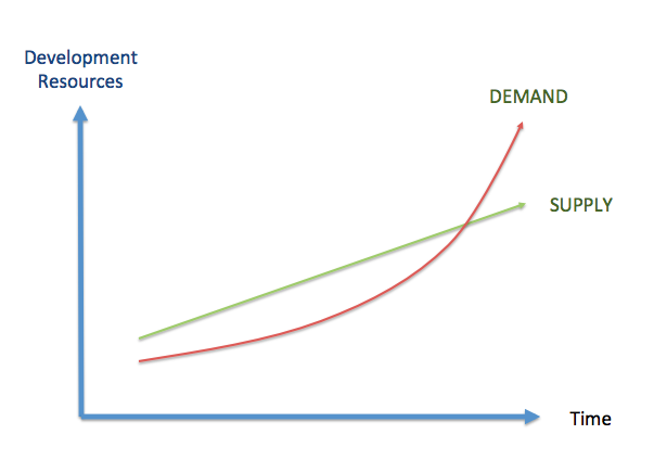
Additionally, as depicted in , the need of software developers has increased exponentially, because more software is needed as software is used in nearly every product with a minimum of complexity. Whereas the need of developers has increased exponentially, the availability of developers has unfortunately not grown at the same pace, i.e. there are less developers than what is needed. Due to that, people without the right skills have started developing software, with the believe that developing software is an easy task that nearly everybody could do. Developing software with people not properly trained or without the right skills inherently leads to bad quality software.
Legal Warranties
Mortenson, a construction contractor purchased software from Timberline Software Corporation, which Timberline installed in Mortenson's computers. Mortenson, relying on the software, placed a bid which was $1.95 million too low because a bug in the software of which Timberline was aware. The State of Washington Supreme Court ruled in favour of Timberline Software. However, a simple bug in the software lead to multiple problems to both companies. In the US Warranty Laws, the Article 2 of the Uniform Commercial Code includes the "Uniform Computer Information Transaction Act" UCITA) that allows software manufacturers to:
- Disclaim all liability for defects
- Prevent the transfer of software from person to person remotely
- Disable licensed software during a dispute
That act, practically means that software distributors can limit their liability through appropriate clauses in the contracts. For instance, below is shown the disclaimer of warranties of a Microsoft product. Although the law overprotects software developers and distributors, using these disclaimers may prevent legal problems, but there are multiple additional problems related with poor software that are not avoided by them.
DISCLAIMER OF WARRANTIES. TO THE MAXIMUM EXTENT PERMITTED BY APPLICABLE LAW, MICROSOFT AND ITS SUPPLIERS PROVIDE TO YOU THE SOFTWARE COMPONENT, AND ANY (IF ANY) SUPPORT SERVICES RELATED TO THE SOFTWARE COMPONENT ("SUPPORT SERVICES") AS IS AND WITH ALL FAULTS; AND MICROSOFT AND ITS SUPPLIERS HEREBY DISCLAIM WITH RESPECT TO THE SOFTWARE COMPONENT AND SUPPORT SERVICES ALL WARRANTIES AND CONDITIONS, WHETHER EXPRESS, IMPLIED OR STATUTORY, INCLUDING, BUT NOT LIMITED TO, ANY (IF ANY) WARRANTIES OR CONDITIONS OF OR RELATED TO: TITLE, NON- INFRINGEMENT, MERCHANTABILITY, FITNESS FOR A PARTICULAR PURPOSE, LACK OF VIRUSES, ACCURACY OR COMPLETENESS OF RESPONSES, RESULTS, LACK OF NEGLIGENCE OR LACK OF WORKMANLIKE EFFORT, QUIET ENJOYMENT, QUIET POSSESSION, AND CORRESPONDENCE TO DESCRIPTION. THE ENTIRE RISK ARISING OUT OF USE OR PERFORMANCE OF THE SOFTWARE COMPONENT AND ANY SUPPORT SERVICES REMAINS WITH YOU.
Although the law overprotects software developers and distributors, using these disclaimers may prevent legal problems, but it is just a way to avoid the legal problems of having bad quality software not solving the real problem that is what affect and frustrates end users.
What is Software Quality?
Many people have tried to define what does Software Quality mean. However, it is not an easy task. Quality in general (not only in Software) is such a subjective topic that trying to define it formally is extremely challenging.
There is a very interesting book called "Zen and the Art of Motorcycle Maintenance" [[ZEN-AND-THE-ART-OF-MOTORCYCLE-MAINTENANCE]] in which the narrator talks about the process of creative writing, and specially about quality. The quality of a written text is difficult to define. If you ask people to rank essays (or programs) from best to worst it is very likely they reach a consensus "they have an intuitive understanding that one essay has more quality than another" but it's much more difficult to identify the parts of the essay that give it quality.
In Zen and the Art of Motorcycle Maintenance, Pirsig (the author) explores the meaning and concept of quality, a term he deems to be undefinable. Pirsig's thesis is that to truly experience quality one must both embrace and apply it as best fits the requirements of the situation. According to Pirsig, such an approach would avoid a great deal of frustration and dissatisfaction common to modern life.
Let's think about another example of how the situation determines the quality. For instance, a master chef has prepared an exquisite meal and invited a group of friends to share it at her restaurant on a lovely summer evening. Unfortunately the air conditioning isn't working at the restaurant, the waiters are surly, and two of the friends have had a nasty argument on the way to the restaurant that dominates the dinner conversation. The meal itself is of the highest quality but the experiences of the diners are not.
You could think that writing code is very different to writing an essay, but that is not the case. Usually, when you have a look at a piece of code it is easy for you to determine if you like it or not, but it becomes quite complicated to assess why.
View 1: Formal Definition
Software quality may be defined as conformance to explicitly stated functional and performance requirements, explicitly documented development standards and implicit characteristics that are expected of all professionally developed software.
This definition emphasis from three points:
- Software requirements are the foundations from which quality is measured: Lack of conformance to requirement is lack of quality.
- Specified standards define a set of development criteria that guide the manager is software engineering: If criteria are not followed lack of quality will almost result.
- A set of implicit requirements often goes unmentioned, like for example ease of use, maintainability, etc.: If software confirms to its explicit requirement but fails to meet implicit requirements,software quality is suspected.
For the first item, explicit software requirements, it is going to be relatively easy to check objectively the conformance to them, for the second one, it is going to be more complicated and depends on how documented those standards are, for the implicit characteristics expected, it is going to be even tougher, as measuring conformance to something that is implicit, is, by definition, impossible.
View 2: The Human Point of View
Those "implicit" requirements mentioned in the formal definition are a hint to indicate that there is something more about Software that goes beyond the explicit requirements. At the end of the day, software is going to be used by people, which do not care about the requirements but about their expectations. Hence, the need to look for another point of view.
"A product's quality is a function of how much it changes the world for the better." [[MANAGEMENT-VS-QUALITY]] or "Quality is value to some person" [[QUALITY-SOFTWARE-MANAGEMENT]]. Both definitions stress that the quality may be subjective. I.e. different people are going to perceive different quality in the same software. The software developers should also think about end users and asking themselves questions such as "How are users going to use the software?".
In order to provide a more complete picture, IEEE standard 610.12-1990 combines both views in their definitions of quality:
Software quality is
- The degree to which a system, component, or process meets specified requirements.
- The degree to which a system, component or process meets customer or user needs or expectations.
View 3: Internal vs. External Quality
There is another dimension of Software Quality that depends on whether we focused on the part of the Software that is exposed to the users or on the part of the Software that is not.
External Quality is the fitness for purpose of the software, i.e. does the software what it is supposed to do?. The typical way to measure external quality is through functional tests and bugs measurement.
Usually this is related to the conformance requirements that affect end-users (formal definition) as well as to meeting the end-user expectations (human point of view).
Some of the properties that determine the external quality of software are:
- Conformance to the product specifications and user expectations.
- Reliability: Is the software working with the same level performance under different conditions and during all the time.
- Accuracy: Does the software do exactly what is supposed to do.
- Ease of use and comfort: Is the software easy to use and responds in an amount time according to user expectations?
- Robustness: Does the software adapt to unforeseen situations, e.g. invalid input parameters, connectivity lost...
Internal Quality is everything the software does but is never seen directly by the end-user. It's the implementation, which the customer never directly sees. Internal quality can be measured by conformance requirements (not focused on end-users but on software structure), software analysis and adherence to development standards or best practices.
If it is not visible to end-user, and our target is make customers happy, we could ask ourselves if Internal Quality is something we should pay attention to.
Internal quality is related with the design of the software and it is purely in the interest of development. If Internal quality starts falling, the system will be less amenable to change in the future. Due to that, code reviews, refactoring and testing are essential as otherwise the internal quality will slip.
An interesting analogy with debts and bad code design was developed Ward [[DEBT-ANALOGY]]. Sometimes companies need to get some credit from the banks in order to be able to invest, however, it is also critical to understand that is impossible to ask for credit continuously as the paying interest will kill the company financially. The same could be used for software, sometimes it is good to assume some technical debt to achieve a goal, for instance, meeting a critical milestone to reach users before our competitors, but it is important to understand that assuming technical debt endlessly would kill the project as it will make the product unmaintainable.
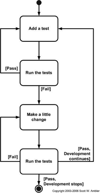
Sometimes, after achieving the target External Quality, we need to refactor our code to improve the Internal Quality. Software Quality is sometimes the art of a continuous refactor.
Let's go back to the analogy of writing an essay or a paper, in that case most people write out the first draft as a long brain-dump saying everything that should be said. After that, the draft is constantly changed (refactored) until it is a cohesive piece of work.
When developing software (for instance in University assignments :-D) the first draft is often finished when it meets the general requirements of the task. So, after that, there is an immediate need to refactor the work into a better state without breaking the external quality. Maybe writing software is also kind of an art?
This is universally true, and the danger of not paying attention to refactor your code is bigger on a larger project where poor quality code can lose you days in debugging and refactoring.
Some of the properties that enable the process of product with good internal quality are:
- Concision: The code does not suffer from duplication.
- Cohesion: Each [module|class|routine] serves a particular purpose (e.g. it does one thing) and does it well.
- Low coupling: Minimal inter-dependencies and interrelation between objects and modules.
- Simplicity: The software is always designed in the simplest possible manner so that errors are less likely to be introduced.
- Generality: Specific solutions are only used if they are really needed.
- Clarity: the code enjoys a good auto-documentation level so that it is easy to be maintained.
The external quality is sometimes compared with "Doing the right things" as opposed to "Doing the things right" which should define what internal quality is.
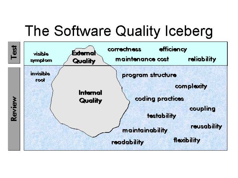
Usually, the problems with the external quality characteristics (correctness, reliability...) are simply visible symptoms about software problems, that usually are related with internal quality attributes: program structure, complexity, coupling, testability, reusability, readability, maintainability... Sometimes, when the internal quality is bad, external quality can be met during a short period of time, but in the longer term, the external quality will be affected.
An excellent analogy is the Quality Iceberg created by Steve McConell (see ).
View 4: ISO 9126
ISO 9126 defines Software Quality as the totality of characteristics of an entity that bears on its ability to satisfy stated and implied needs.
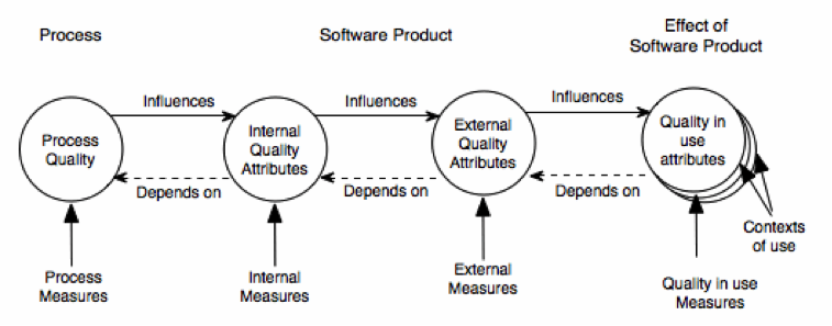
It recognizes that quality is not only determined by the software itself but also by the process used for software development and the use made of the software. Hence, the following identities are defined:
- Quality of the process of constructing software: process quality
- Quality of software product in itself: internal and external quality
- Quality of software product in use: quality in use
ISO identified 6 characteristics of the software quality that are sub-divided into sub-characteristics:
- Functionality: A set of attributes that bear on the existence of a set of functions and their specified properties. The following sub-characteristics were defined: Suitability, Accuracy, Interoperability and Security.
- Reliability: A set of attributes that bear on the capability of software to maintain its level of performance under stated conditions for a stated period of time. The following sub-characteristics were defined. The following sub-characteristics were defined: Maturity, Fault Tolerance and Recoverability.
- Usability: A set of attributes that bear on the effort needed for use. The following sub-characteristics were defined: Understandability, Learnability and Operability.
- Efficiency: A set of attributes that bear on the relationship between the level of performance of the software and the amount of resources used. The following sub-characteristics were defined: Time Behaviour and Resource Behaviour.
- Maintenability: A set of attributes that bear on the effort needed to make specified modifications. The following sub-characteristics were defined: Analyzability, Changeability, Stability and Testability.
- Portability: A set of attributes that bear on the ability of software to be transferred from one environment to another. The following sub-characteristics were defined: Adaptability, Installability, Conformance and Replaceability.

Quality in use is defined by ISO as "the extent to which a product used by specified users meets their needs to achieve specified goals with effectiveness, productivity, and satisfaction in specified contexts of use". The quality in use hence depends on the context in which the product is used and its intrinsic quality.
Summary
There is no a single definition of quality. However, the importance of Software Quality is continuously increasing. The concepts of external and internal quality are commonly used across the software industry, but despite that, the properties used to measure the quality diverge across different methodologies, standards or companies.
Key Definitions
Despite the availability of different quality definitions, characteristics and entities, a common understanding is that high quality is usually linked to products with low number of defects. Therefore, it is assumed that a quality problem is due to the impact of a defect.
But in order to identify which is high quality, defining what a defect is needed. In general, there are three concepts used in software quality to refer to defects:
- Failure: Any deviation of the observed behaviour from the specified behaviour.
- Error: System state where any further processing by the system will lead to a failure.
- Fault: Algorithmic cause of an error. (Also known as bug or defect).
            Peter is driving his car towards Oxford. While he is driving, the road
            diverts into two different directions:
              1.  Left road to Oxford
              2.  Right road to Cambridge

            By mistake, Peter takes the road to Cambridge. That is a fault that is
            committed by Peter.

            Suddenly, Peter is in an error situation or state: Peter is heading
            Cambridge and not Oxford.

            If Peter goes on and arrives to Cambridge, that would be a failure:
            Peter was planning to get to Oxford but he has arrived to Cambridge instead.

            If Peter realizes of the error situation while he is driving Cambridge,
            returns to the junction and takes the right road to Oxford no failure
            would happen as Peter recovers from the error condition.
            public static int numZero (int[] x) {
              // effects: if x == null throw NullPointerException
              // else return the number of occurrences of 0 in x
              int count = 0;
              for (int i = 1; i < x.length; i ++) {
                if (x[i] == 0) {
                 count ++;
                }
              }
              return count;
            }
The fault in the code above is that it starts looking for zeroes at index 1 instead of index 0. For example, numZero([2, 7, 0]) correctly evaluates to 1, while numZero([0, 7, 2]) incorrectly evaluates to 0. In both cases the fault is present and is executed. Although the code is in both cases in an error situation, only in the second case there is a failure: the result is different from the expected one. In the first case, the error condition (the for starts in 1) do not propagates to the output.
Some early conclusions can be already identified:
- For a given fault, not all the inputs to the software will "trigger" the fault to create a failure. In some situations, the failure will not appear to the end-user, despite the fault is in the code.
- Identifying a fault given an observed failure is, in some situations, very difficult, as multiple entities within the code (objects, methods, attributes) may be involved and the fault may occur in any of them.
Software Quality Assurance
Introduction to SQA
Software Quality Assurance (SQA) is the set of methods used to improve internal and external qualities. SQA aims at preventing, identifying and removing defects throughout the development cycle as early as possible, as such reducing test and maintenance costs.
SQA consists of a systematic, planned set of actions necessary to provide adequate confidence that the software development process or the maintenance process of a software system product conforms to established functional technical requirements as well as with the managerial requirements of keeping the schedule and operating within the budgetary confines.
The ultimate target of the SQA activities is that few, if any, defects remain in the software system when it is delivered to its customers or released to the market. As it is virtually impossible to remove all defects, another aim of QA is to minimize the disruptions and damages caused by these remaining defects.
The SQA methodology will also depend on the software development methodology used, as they are inherently couple. For instance, different software development models will focus the test effort at different points in the development process. Newer development models, such as Agile, often employ test driven development and place an increased portion of the testing in the hands of the developer, before it reaches a formal team of testers. In a more traditional model, most of the test execution occurs after the requirements have been defined and the coding process has been completed.
An example of an SQA methodology is available at [[IEEE-QA-TEMPLATE]].
SQA activities are not only carried out by the Software Quality group, the software engineer group is responsible for putting in place the SQA methodology defined, which may include different activities such as testing, inspection, reviews...
SQA Activities
Classification SQA Activities
The activities that are carried out as part of the SQA process can be divided in three different categories.
-
Defect Prevention: Defect prevention consists on preventing
certain types of faults from being injected into the
software. As explained in previous section, a fault is the
missing or incorrect human actions that lead to error
situations in the software. There are two generic ways to
prevent defects:
- Eliminating certain fault sources such as ambiguities or human misconceptions
- Fault prevention or blocking: Breaking the causal relation between error sources and faults through the use of certain tools and technologies.
-
Defect reduction: Consists in removing the faults from the
software through fault detection and removal. These QA
alternatives detect and remove certain faults once they have
been injected into the software systems. The most traditional
QA activities fall into this category such as:
- Inspection: directly detects and removes faults from the software code, design, etc.
- Testing: removes faults based on related failure observations during program execution.
-
Defect containment: Consists in minimizing the impact of the
software faults. The most important techniques in this area
are:
- Fault-tolerance techniques: Try to break the causal relationship between faults and failures. E.g. ensuring that error conditions do not lead to a software failure.
- Containment measures: Once the error has occurred, if there is no way to prevent the failure, ideally, it should be possible to perform some actions to minimize the impact and consequences of the failure.
The following sections explain in detail these SQA activities.
Fault Prevention
The main goal of these activities is reducing the chance for defect injections and the subsequent cost to deal with these injected defects.
Most of the defect prevention activities assume that there are known error sources or missing/incorrect actions that result in fault injections, as follows:
- If human misconceptions: Lack of education.
- If imprecise designs & implementations: Lack of formal methods.
- If non-conformance to standards: No standard enforcement.
- If lack of tools and techniques: No technique or tool adoption.
Education and Training
People is the most important factor that determines the quality and, ultimately, the success or failure of most software projects. Hence, it is important that people involved in the software planning, design and development have the right capabilities for doing their jobs. The education and training effort for error source elimination should focus on the following areas:
- Product and domain specific knowledge.
- Software development knowledge and expertise.
- Knowledge about Development methodology, technology, and tools.
- Development process knowledge.
Formal Methods
Formal methods provide a way to eliminate certain error sources and to verify the absence of related faults. Formal development methods, or formal methods in short, include formal specification and formal verification.
- Formal specification is concerned with producing an unambiguous set of product specifications. An unclear specification implies that the software target and behaviour may depend on the interpretation of the developer, due to that the likelihood of defects in errors is higher.
- Formal verification checks the conformance of software design or code against these formal specifications, thus ensuring that the software is fault-free with respect to its formal specifications.
Fault Removal
Even if the best software developers in the world are involved in a software project, and even if they follow the formal methods described in the previous section, some faults will be injected in the software code. Due to that, defect prevention needs to be complemented with other techniques focused on removing as many of the injected faults as possible under project constraints.
Fault distribution is highly uneven for most software products, regardless of their size. Much empirical evidence has accumulated over the years to support the so-called 80:20 rule, which states that 20% of the software components are responsible for 80% of the problems (Pareto Law). There is a great need for risk identification techniques to detect the areas in which the fault removal activities should be focused.
There are two key activities that deal with fault removal: Code Inspection and Testing.
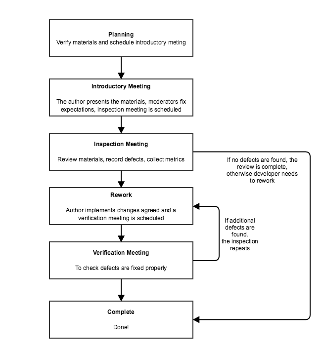
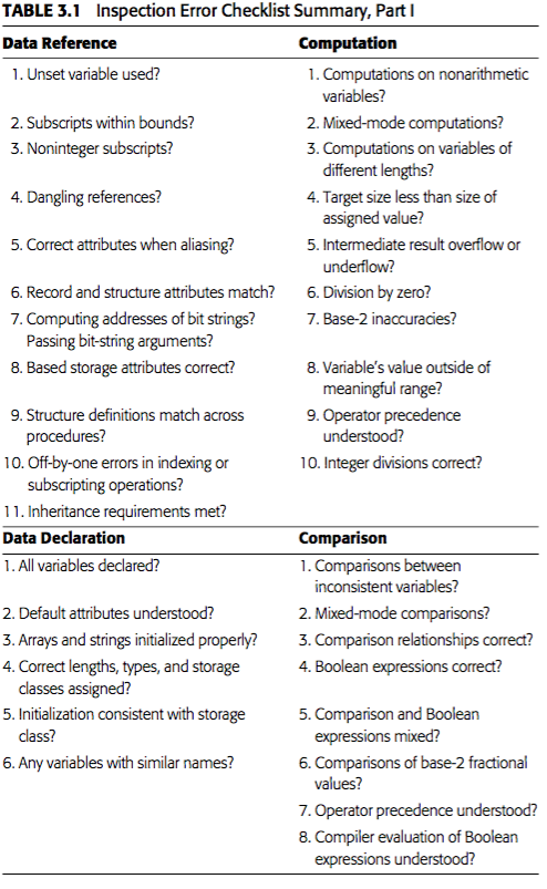
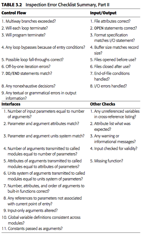
Inspections
The software inspections were first introduced by Michael E. Fagan in 1970s, when he was a software development manager at IBM. The inspections are a means of verifying intellectual products by manually examining the developing product, a piece at a time, by small groups of peers to ensure that it is correct and conforms to product specifications and requirements. Inspections may be done in the software code itself and also in other related items such as design or requirements documents.
Code inspections should check for technical accuracy and completeness of the code, verify that it implements the planned design, and ensure good coding practices ?and standards are used. Code inspections should be done after the code has been compiled and all syntax errors removed, but before it has been unit tested.
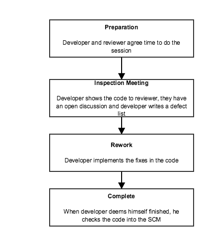
There are different kind of inspections depending on factors such as the formality (formal vs informal) the size of the team (peer review, team review), whether it is guided or not; The type of inspection to be done depends on the software to be reviewed, the team involved and the target of the review.
Regardless of the inspection type used, there are clear benefits when inspections are used. For instance, according to Bell-Northen Researh, the cost of detecting a defect is much lower in case of inspections (1 hour per defect) than in the case of testing (2-4 hours per defect).
More information about inspections can be found at [[INSPECTIONS-AND-REVIEWS]] and [[TRUTHS-PEER-REVIEWS]] and in the last chapter.
Testing
Testing is the execution of software and the observation of the program behaviour and outcome. As in the case of the software inspections, there are different kind of testing, usually applied in different phases of the software development process.
Some of the most typical testing types are:
- Unit Testing: individual units of source code are tested to determine if they are fit for use. A unit is the smallest testable part of an application.
- Module Testing: A complete module is tested to determine if it fulfils its requirements.
- Integration Testing: Any type of software testing that seeks to verify the interfaces between modules against a software design.
- System Testing: It tests a completely integrated system to verify that it meets its requirements
- Acceptance Testing: Testing performed often in production or pre-production environment to check that the software is ready for being delivered and deployed.
A concept tight related with testing (although applicable in other areas such as reviews) is the handling of the defects. In particular it is very important that the defects detected are properly recorded (defect logging) with all the relevant information as in many situations finding the error related with a fault is not trivial. It is also very important that the issues detected are monitored so that everybody knows what is the status of every defect after the initial discovery (defect tracking).
Defect Containment
The defect reduction activities can only reduce the number of faults to a fairly low level, but not completely eliminate them. For instance, in many situations, the combination of possible situations is so big, that it is impossible to test all those situations, especially those linked to rare conditions or unusual dynamic scenarios.
Depending on the purpose of the software, these remaining faults, and the failure risk due to them may be still inadequate, so some additional QA techniques are needed:
- Software fault tolerance.
- Failure containment.
For instance, the software used in the flight control systems is one example of software with very extreme requirements about failures. The report [[CHALLENGES-FAULT-TOLERANT-SYSTEMS]] provides more details about the challenges that this kind of systems pose to software developers.
Software Fault Tolerance
Software fault tolerance ideas originate from fault tolerance designs in traditional hardware systems that require higher levels of reliability, availability, or dependability.
All fault tolerance systems must be based on the provision of useful redundancy that allows to switch between components when one of they fail (due to software or hardware faults). That implies that there has to be some extra components, which ideally should have a different design to avoid the same error to happen twice. Based on how those redundant components structured are used (e.g. when to switch from one to another) there are different kind of systems:
-
Recovery blocks: Use repeated executions (or redundancy over
time) as the basic mechanism for fault tolerance. The
software includes a set of "recovery points" in which the
status is recorded so that they could be used as fallbacks in
case something goes wrong. When a piece of code is executed,
a "test acceptance" is internally executed, if the result is
OK, a new "recovery point" is set-up, if the result is not
acceptable, then the software returns to the previous
"recovery point" and an alternative to the faulty code is
enacted. This process continues until the "acceptance test"
is passed or no more alternatives are available, which leads
to a failure. Some key characteristics about this scheme that
is depicted in :
- It is a backward error recovery technique: when an error occurs, appropriate actions are taken to react but no preventing action is taken.
- It is a "serial technique" in which the same functionality (the recovery block) is never executed in parallel.
- The "acceptance test" algorithm is the critical part to success as well as the availability of recovery blocks designed in different ways to the original code.
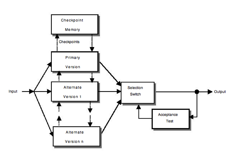
Recovery Blocks -
NVP (N-version programming):
This technique uses parallel redundancy, where N copies, each of a different version, of codes fulfilling the same functionality are running in parallel with the same inputs. When all of those N-copies have completed the operation, an adjudication process (decision unit) takes place to determine (based in a more or less complex vote) the output.
Some key characteristics about this scheme that is depicted in
- It is a forward error recovery technique: preventive actions are taken. Even if no error occurs the same functionality is executed multiple times.
- It is a "parallel technique" in which the same functionality is always executed in parallel by different versions of the same functionality.
- The "decision unit" algorithm is the critical part to success as well as the availability of different versions of the same code designed in different ways.
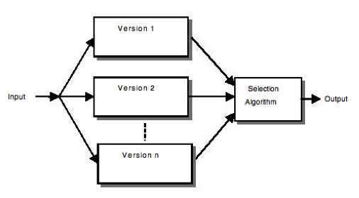
N version programming Obviously a wide range of different variants of those systems have been proposed based in multiple combinations of them [[COST-EFFECTIVE-FAULT-TOLERANCE]] and multiple comparisons between the performance are also available [[PERFORMANCE-RB-NVP-SCOP]].
What do you think are the key advantages and disadvantages of the two fault tolerance techniques described (Recovery Blocks & N-Version)? Exercise 3: Recovery Blocks vs. N-Version
Failure Containment
There is software that is used in safety critical systems, that have severe consequences in case a failure occurs. In those situations it is very important to avoid some of the potential accidents or at lt
Various specific techniques are used for this kind of systems, most of them based on the analysis of the potential hazards linked to the failures:
- Hazard Elimination through substitution, simplification, decoupling, elimination of specific human errors and reduction of hazardous materials or conditions. These techniques reduce certain defect injections or substitute non-hazardous ones for hazardous ones. The general approach is similar to the defect prevention and defect reduction techniques surveyed earlier, but with a focus on those problems involved in hazardous situations.
- Hazard Reduction through design for controllability (for example, automatic pressure release in boilers), us of locking devices (for example, hardware/software interlocks), and failure minimization using safety margins and redundancy. These techniques are similar to fault tolerance, where local failures are contained without leading to system failures.
- Hazard control through reducing exposure, isolation and containments (for example barriers between the system and the environment), protection systems (active protection activated in case of hazard), and fail-safe design (passive protection, fail in a safe state without causing further damages). These techniques reduce the severity of failures, therefore weakening the link between failures and accidents.
- Damage control through escape routes, safe abandonment of products and materials, and devices for limiting physical damages to equipment or people. These techniques reduce the severity of accidents, thus limiting the damages cause by these accidents and related software failures.
Notice that both hazard control and damage control above are post-failure activities that attempt to "contain" the failures so that they will not lead to accidents or the accident damage can be controlled or minimized. All these techniques are usually very expensive and process/technology intensive, hence they should be only applied when safety matters and deal with rare conditions related to accidents.
Software Quality Engineering
Whereas Quality Assurance defines a set of methods to improve Software Quality, it does not define aspects that are key in order to ensure good quality software is delivered such as:
- What is the Quality Target? I.e. when to stop and deliver the software
- How can that quality target be checked.
- Are the right QA tasks being done at the right time?
- Are the QA tasks being executed right?
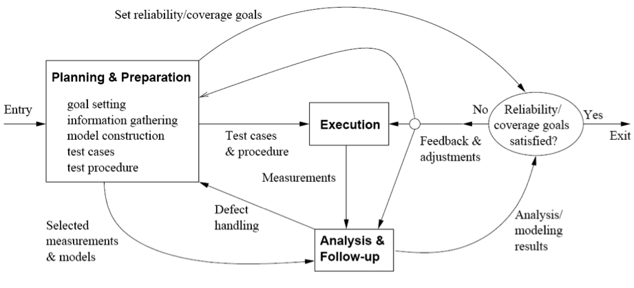
In order to address these questions, the QA activities should be considered not in an isolated manner, but as part of a full engineering problem. Software Quality Engineering is the discipline that defines the processes to ensure high quality products. QA activities are only a part of that process, which requires further activities such as Quality Planning, Goal Setting or Quality Assessment. The provides an overview of the typical SQE:
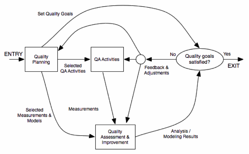
Pre-QA Activities: Quality Planning
Before doing any QA activity, it is important to consider some aspects such as the target quality, the most appropriate QA activities to be done and when should be done, how are the quality going to be measured. All those activities are usually called Pre-QA or Quality Planning Activities.
The first activity that should be done in SQE is defining what are the specific quality goals for the software to be delivered. In order to do so, it is important to understand what are the expectations of the software end-user/customer. Obviously, it is also key to recognize that the budget is limited and that the quality target should be financially doable. The following activities are key to identify the target quality of the software:
- Identify quality views and attributes meaningful to target customers and users. Which aspects will be key for them to perceive the software as high quality one? This may depend a lot on the type of product and on the target customers.
- Select direct quality measures that can be used to measure those quality attributes that are key for the customers.
- Quantify these quality measures to set quality goals while considering the market environment and the cost of achieving different quality goals.
Once that the quality goals are clear, the QA strategy should be defined. Two key decisions should be made during this stage:
- Which QA activities are the most adequate ones to meet the customer quality expectations. For doing this, it is important to translate the quality views, attributes and goals into the QA activities to be performed. It is also very important to determine when every QA activity is going to be executed as part of the full Software Development Process.
- The external quality measures should be mapped into internal indirect ones via selected quality models. Good models are required in order to predict external quality based on internal indicators. It is also very important to identify how the results of this measure are going to be collected and used (e.g. what happens if the quality is not good enough or how the feedback is going to be used).
In-QA Activities
These activities have been described in section 1.4.2 and basically consist in executing the QA activities planned and handling the defects discovered as a result of them.
Post-QA Activities
These activities consist in measuring the quality of the software (after the QA activities), assess the quality of the software product and the definition of the decisions and actions need to improve its quality.
All these activities are usually carried out after normal QA activities have started but as part of these "normal" QA activities. Their goal is to provide feedback so that decisions can be made and improvements can be suggested. The key activities include:
- Measurement: Besides the direct measure of tracking the defects during the in-QA activities, various other measurements are needed in order to the track the QA activities and for project management purposes. The data resulting from this analysis is important to manage software project and quality.
- Analysis and Modelling: These activities analyse measurement data from software projects and fit them to analytical models that provide quantitative assessment of selected quality characteristics and sub-characteristics. This is key to obtain an objective assessment of the current product quality, predict future quality or identify problematic areas.
- Providing feedback and identifying improvement potentials: The results of the previous activities can lead to some suggestions to improve the process followed with the software being assessed (e.g. more testing resources are needed, test cases are not sufficient...) or the general SQE methodology.
- Follow-up Activities: Besides immediate actions, some actions resulting from the analysis may require a longer time. For instance, if major changes are suggested to change the SQE process, they cannot be usually implemented while the current process has not finished.
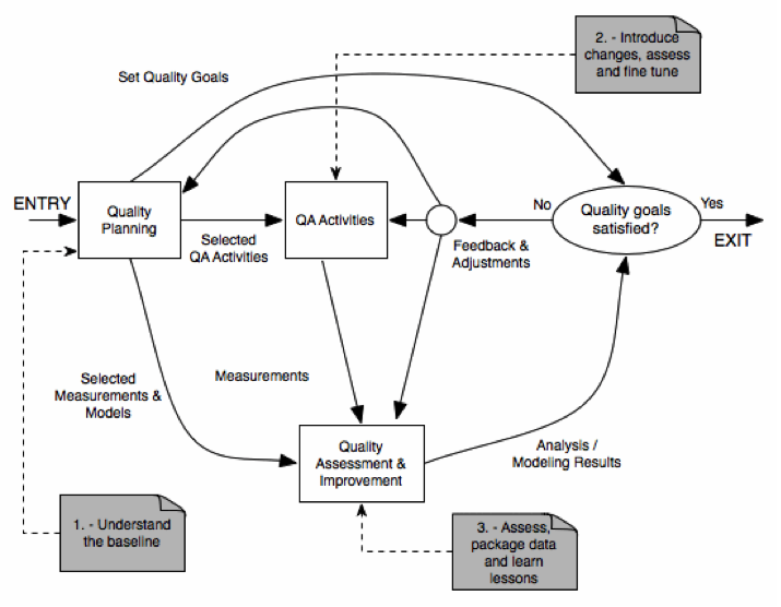
Quality Improvement Process (QIP)
The overall framework for quality improvement is called QIP, and it includes three interconnected steps:
- Understand the baseline so that improvement opportunities can be identified and clear, measurable goals can be set.
- Introduce process changes through experiments, pilot projects, assess their impact, and fine tune these process changes.
- Package baseline data, experiment results, local experience, and updated process as the way to infuse the findings of the improvement program into the development organization
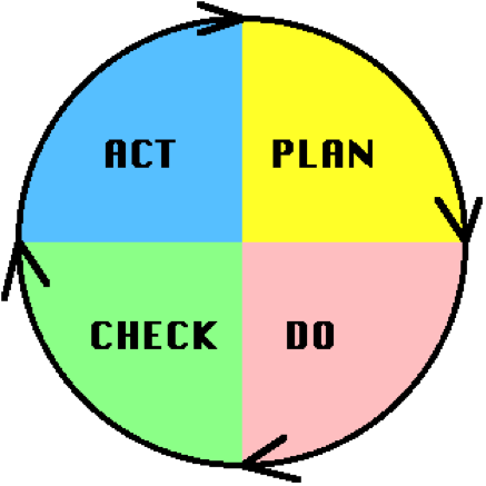
The Deming Quality Cycle
W. Edwards Deming in the 1950's proposed that business processes should be analysed and measured to identify sources of variations that cause products to deviate from customer requirements. He recommended that business processes be placed in a continuous feedback loop so that managers can identify and change the parts of the process that need improvements. As a teacher, Deming created a (rather oversimplified) diagram to illustrate this continuous process, commonly known as the PDCA cycle for Plan, Do, Check, Act:
- Plan Quadrant: one defines the objectives and determines the conditions and methods required to achieve them.
- Do Quadrant: the conditions are created and the necessary training to execute the plan is performed (new procedures). The work is then performed according to these procedures.
- Check Quadrant: One must check to determine whether work is progressing according to the plan and whether the expected results are obtained.
- Action Quadrant: If the checkup reveals that the work is not being performed according to plan or results are not what was anticipated, measures must be devised for appropriate action.
Deming's PDCA cycle can be illustrated as in :
By going around the PDCA circle, the working methods are continuously improved as well as the results obtained. However, it is important to take care avoid a situation called "spiral of death" It happens when an organization goes around and around the quadrants, never actually bringing a system into production.
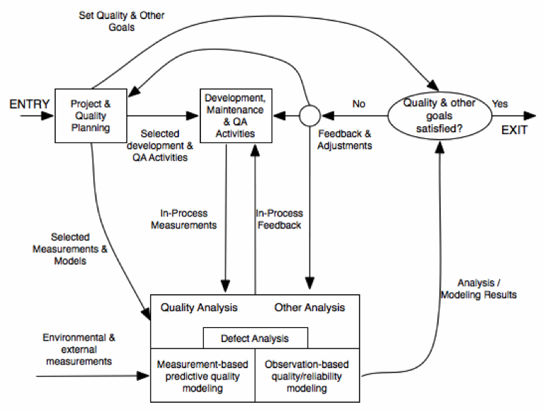
QE in Software Development Process
The quality engineering process cannot be considered in an isolated manner, but as part for the overall software engineering process. For instance, most of the SQE Activities should be included as part of the Software Development activities ():
- Quality Planning should be part of product planning.
- In-QA activities should be part of the development activities.
- The Quality Analysis/Feedback should be part of the project management responsibilities.
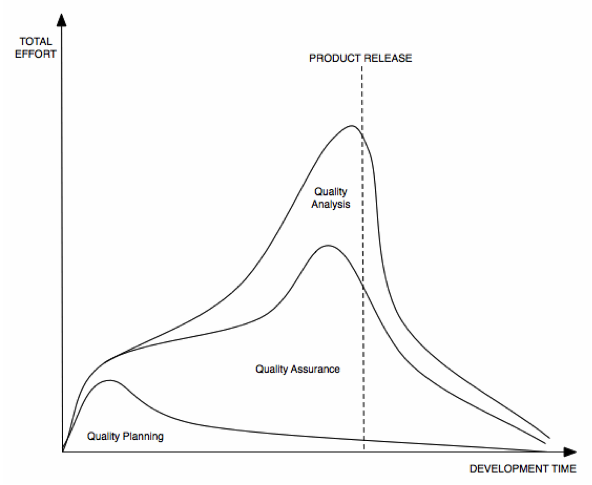
However, it should be considered that SQE activities have different timing requirements, activities and focus. For instance, represents the typical effort spent in the different quality activities during the software development time.
Focusing on the QA activities, in a typical waterfall development model, the provides an estimate of the key QA activities done during each of the project phases:

Another important aspect to be considered is that some of the QA activities cannot be done until it is already too late. For example, for safety critical systems, post-accident measurements provide a direct measure of safety, but due to the damage linked to those accidents, they should be avoided by all means. In order to take early measures, appropriate models that link some of the quality measures during the development process with the end product quality are needed. Last but not least, it should be stressed that there is an increasing cost of fixing problems late instead of doing early, because a hidden problem may lead to other related problems, and the longer it stays in the system, the discovery is more difficult.
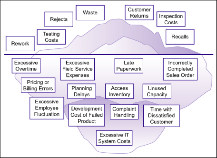
The cost of quality
In section 1.1, some of the implications of bad quality software have been introduced. The cost of poor quality (COPQ) is not the only cost that Software Quality Engineering should take into account. The cost of having good quality (COGQ) that may be linked to SQA activities (e.g testing or code inspections) should not be underestimated and considered when the total quality cost is assessed.
As in the case of the external and internal quality, the different costs linked to quality have been represented by some authors as an iceberg, in which some of the costs are easy to be identified (e.g. testing costs, customer returns...) while some others are not always taken account (e.g. unused capacity, excessive IT costs...). In [[COST-OF-QUALITY]] there is a detailed analysis of this approach for identifying quality costs.